
|
|
|
![]()
Contents
Re-figure resultsThis write-up describes my experiences of sending my 12.5" Cass mirror set to John Nichol for re-figuring and the subsequent learning and set-up to put it back in the scope and set it up for imaging use. Once John had received the mirrors, which took me a few weeks to whittle a box to send them to him out of solid wood into a bespoke container we discussed over the telephone what to do and after his initial testing, he recommended aiming for a RC configuration due to the very fast (f/2.7) nature of the primary otherwise. This meant the primary could go slightly slower while the secondary compensated to achieve a very similar format - 12.5" f/9 in the same tube size. John shared his ronchi results, we agreed it looked good and he sent it off to Orion for aluminising. To recollect, this mirror set is from George Hole and Sons of Brighton. The primary is a 12.5" f/2.7 and the secondary is 92mm diameter and its CoC is unknown. You can see the scope below, on the kitchen table, ready for mechanical alignment, again.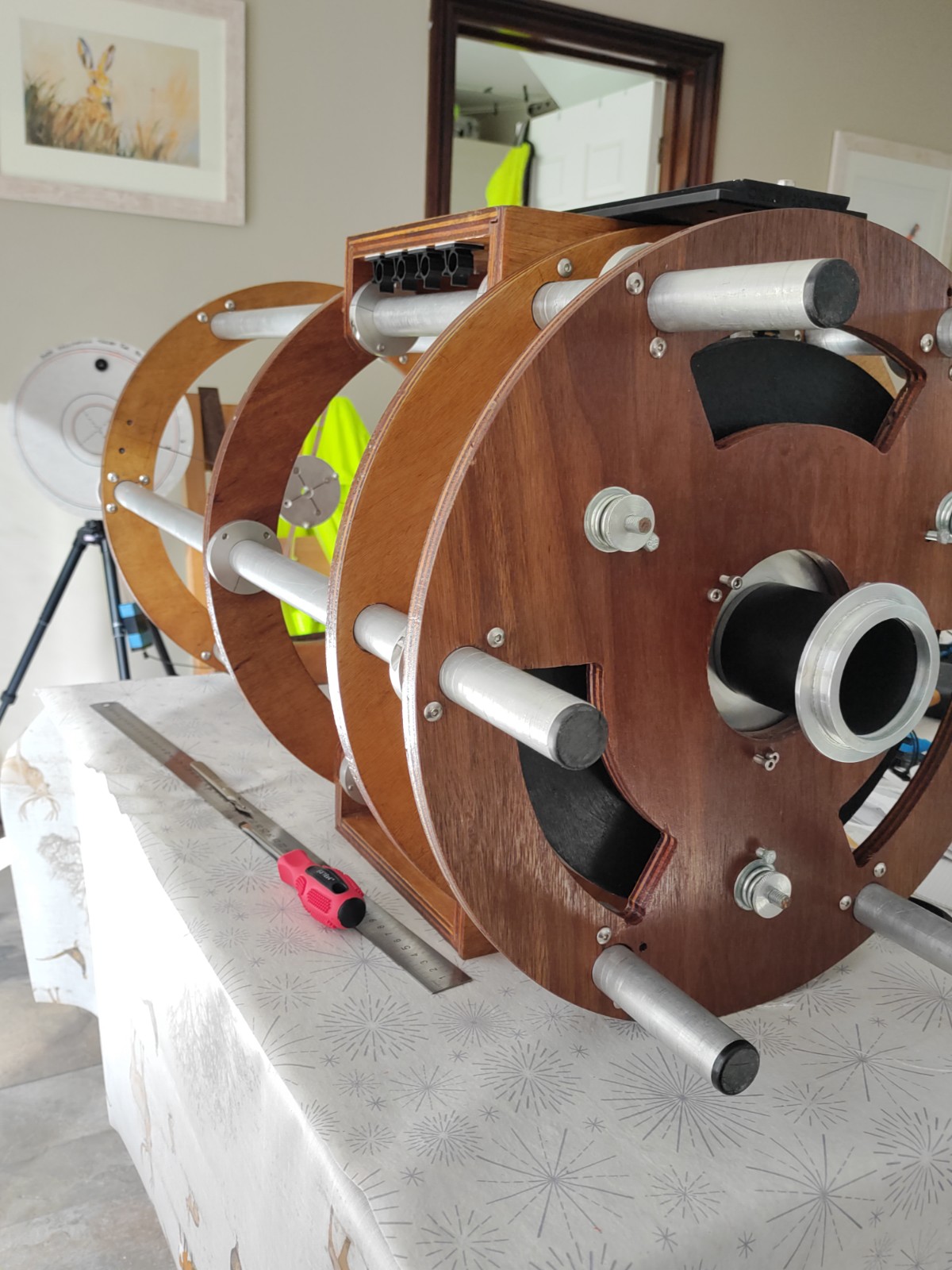
Telescope StatsThe new RC design specifications are shown in the figure below. 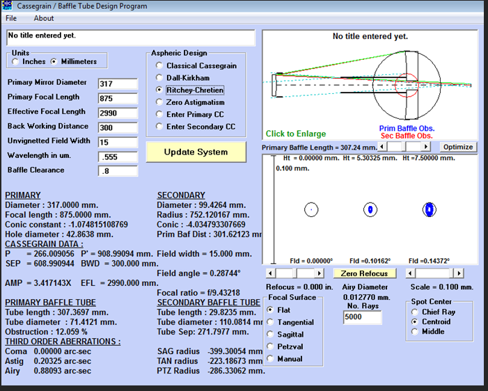
The telescope spot diagrams below show the difference between the original cassegrain format and the new RC format. The RC should show no coma or spherical abberation and instead presents a slightly more curved field and symmetric astigmatism off-axis. The Cassegrain spot diagram 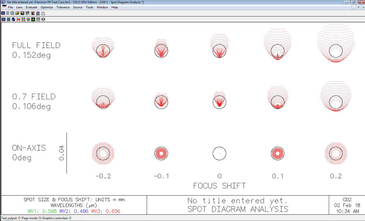
The expected RC spot diagram 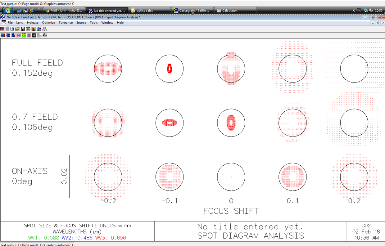
Optics alignmentThe optics and their perfect collimation to create the best image possible are subject to a wide range of different effects:
So I address this methodically :
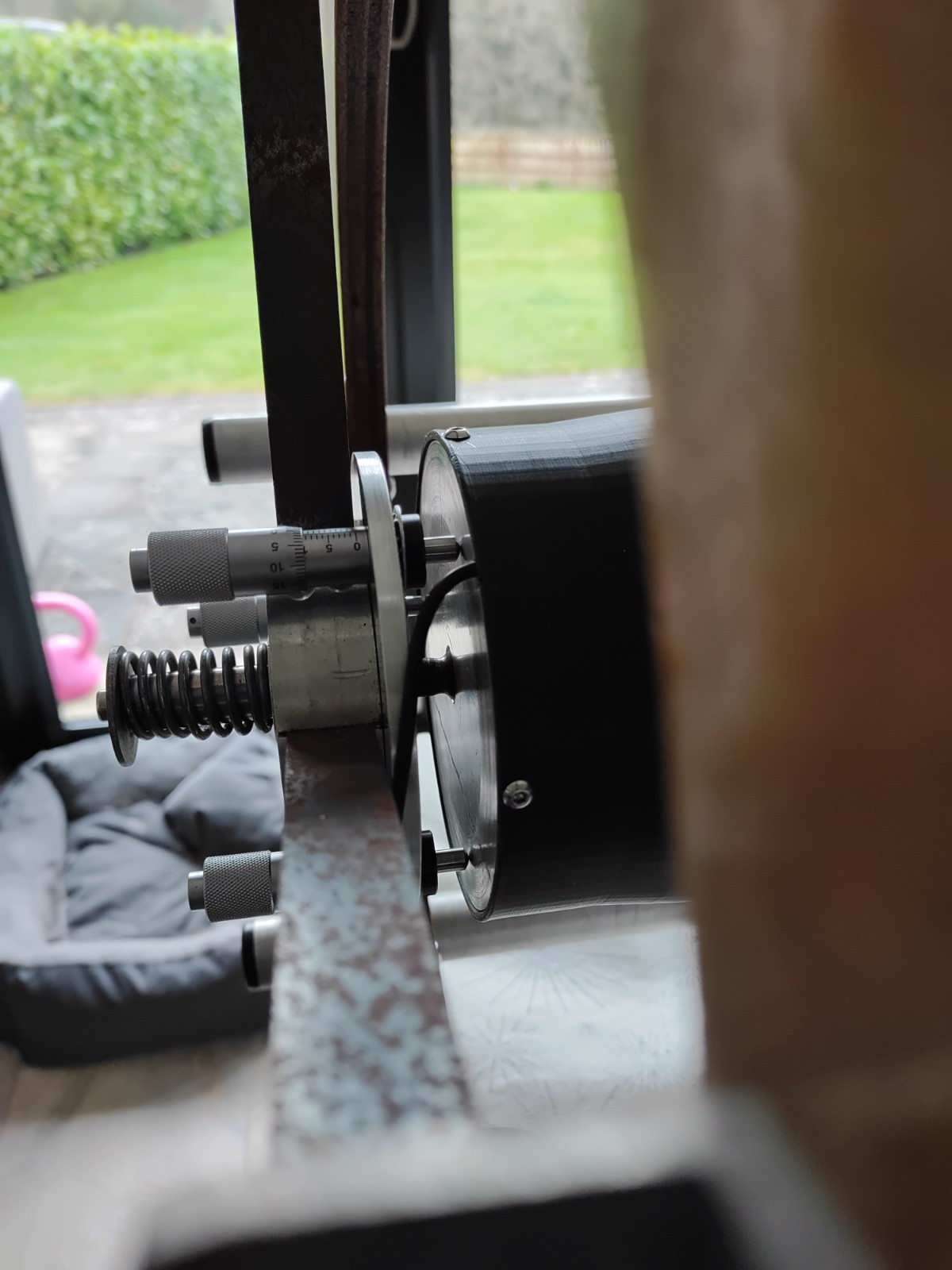
Setup the framesThe first action is to ensure that the frames are straight with respect to a reference - in this case my dining table. I put the scope on the table and used a roofers square to check the frames were perfectly upright in their fastened position. A mild tap with the mallet moves them along the tube frame until they are and then re-fasten the tube clamps. I do in one axis and then rotate the tube through 90° to check the other axis. Iterate and then I'm happy. This pic shows the process using the roofers square. Centre the secondaryThe next is to define the secondary mount as the front end of the optical axis and mechanical axis. The secondary mount is located using the spider vane adjusters. The spider vanes don't like being out of square and there's not a lot of adjustment available. Fortunately, it seems to be in the right place, by measuring the centre with a rule with respect to the frame aperture. Using the adjusters to bring the secondary mount centre to the measured centre of the mirror is the best I can do here. Fixup the secondary to be symmetric and spotted centrallyWhile I centred the secondary I noticed that the secondary mirror backing plate, which uses a 13mm ball rod-end to pivot on, was not very central or well-formed. So I chucked it up in the lathe and re-drilled the central hole, finishing with a 15mm drill to re-drill and re-seat the ball head. The ball head itself I chopped in half with an angle grinder to make the head low-relief so it doesn't press on the back of the secondary mirror itself. Afterwards the mirror mount was now reliably central, rotationally centred and free in movement. I also turned down the mirror backing plate to suit the new mirror diameter and replaced the secondary mounting cage with a purpose-designed 3d-printed enclosure in PLA which also provided the secondary baffle. The mirror assembly also includes a film heater for keeping the secondary dew-free which will be powered from the ALPACA Cover Calibrator device The final icing on the plate was to replace the adjustment screws which had a particularly bad threading with new ones - I replaced the backing plate that held the screws and then replaced the screws themselves with cheap micrometer heads with domed ends. Drilling 9.5mm holes for each micrometer meant they fit snugly through the holes and bolted using star washers on the underside for a firm and calibrated fit. I now have adjusters which provide 0.5mm per rev and very positive, smooth operation. the last part of this operation is to re-spot the secondary. I cut a template from paper, punched the centre and then used that as an overlay to let me apply an ink spot to the centre of the mirror through the hole for use in alignment and collimation. In the picture you can see the central boss and the 4 vanes of metal strapping, through which the secondary mounting pivot is pulled by the spring, the backing plate carries the micrometers and operate against the rear of the secondary mirror container. 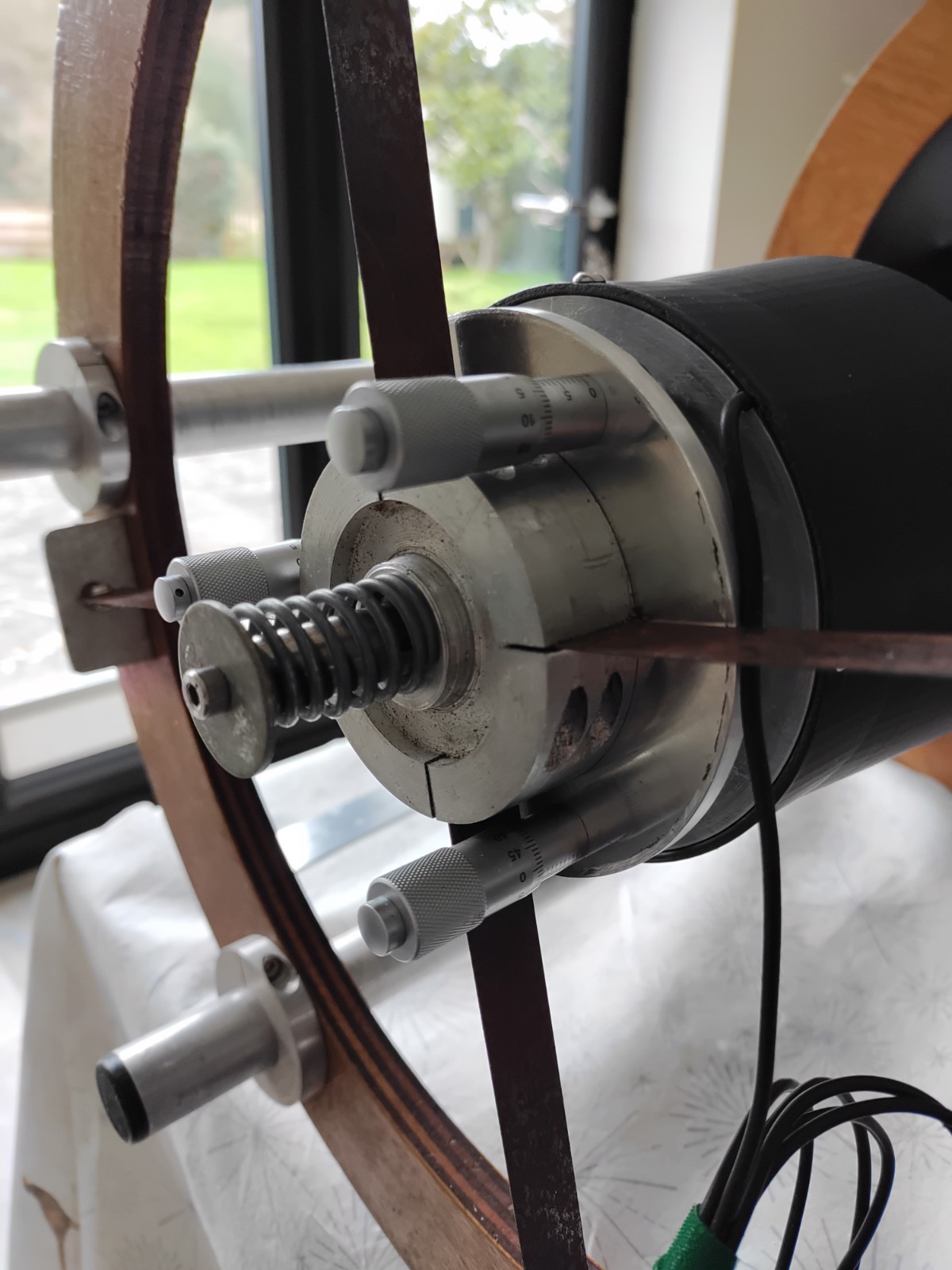
Align the focuserThe next thing to do should be to align the focuser with the centre of the secondary mount. To do this I really want a bore sight I can trust to use for alignment. One thing I had been concerned with is that I had built the primary baffle from aluminium tubing and fasten it to the focuser plate using a nylon collar with a turned thread, pressed and glued to the tube. I believed that to be a potentially significant souce of misalignment, since if misaligned, the tube shadow makes collimation by concentrically aligning the reflective surfecs very confusing. I typically remove the primary baffle during collimation for that reason. This time, I actually tested the alignment - I stood it upright on the table along side the telescope and rotated it on its axis. There was no discernable movement. I had threaded the collar on the lathe, parted the tube off from the length on the lathe to get a nice square end and threaded the focuser faceplate screw adapters but even so it was nice to get confirmation that it was actually straight. This image shows the focuser carrier plate with its central threaded screw. On the user side screws the focuser mount dovetail. On the far side screws the primary baffle. 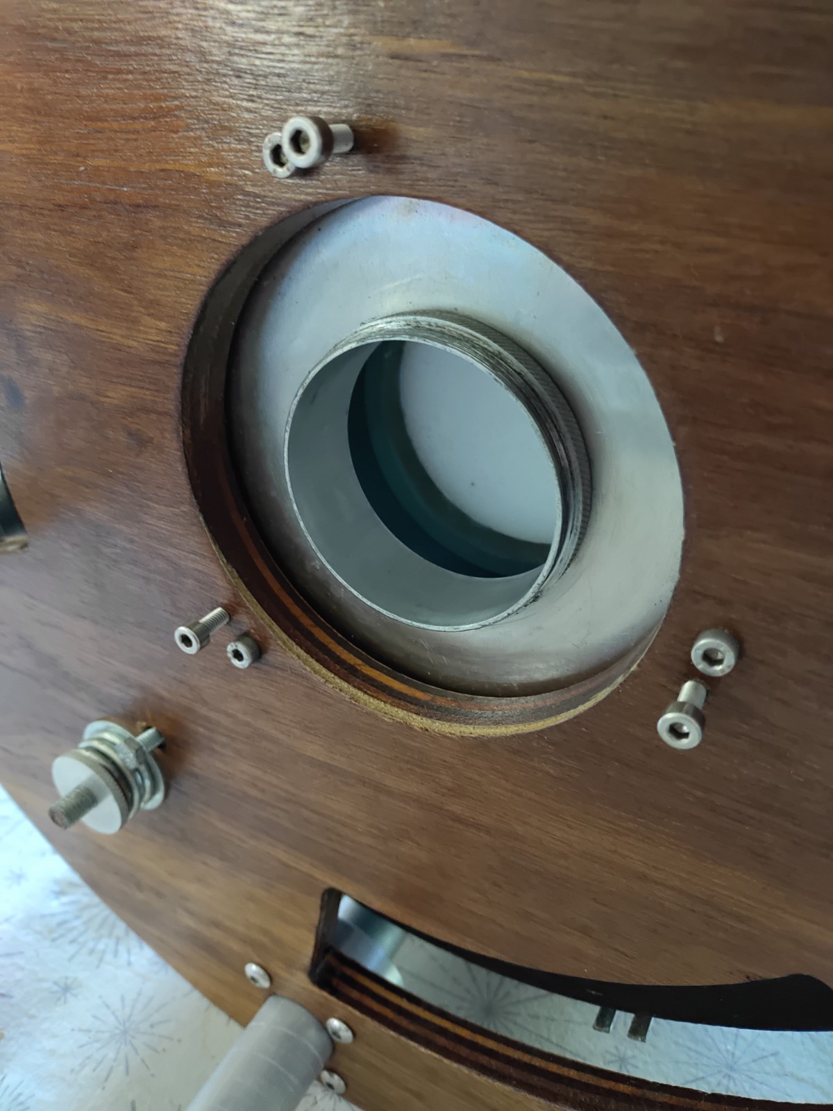
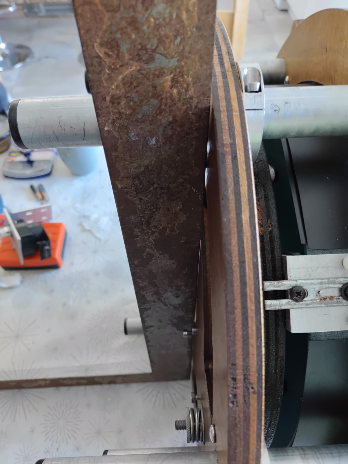
Since the focuser on the tiltable focuser plate is attached to the rear of the mirror carrier frame, the focuser itself is unlikely to be concentric to the mirror and its optical axis without adjustment. In my configuration the primary baffle is mounted directly to the end of the focuser by way of a large screw thread that couples the focuser on one side and the baffle on the other. In mounting the baffle and testing it for straightness, I now believe I can use the concentricity of the mirror to the baffle ( ie the spacing all the way round being the same ), to position the mirror, as long as the mirror is close to the focuser so any deviations from square alignment of the baffle are still small and introduced errors remain small. Any errors introduced here are moving the mechanical axis of the primary mirror away from the mechanical axis of the focuser. Essentially introducing an off-axis viewpoint to the optical axis. at 2000m focal length, an error of 1mm would mean 2' mis-alignment. Now, having already checked the primary baffle is true, I can put a pinhole at the end of the baffle and one at the front of the focuser and line them up with the secondary mount by adjusting the focuser plate push-pull adjusters to ensure I have a long baseline bore sight to give me sensitive alignment. Centre and align the mirrorTo make the mirror concentric to the baffle tube I use a small gauge consisting of a narrow wedge of wood cut at a shallow angle and marked along the edge. In the image you can see the wedge to the right, its reflection below and the mirror clamp to the left. 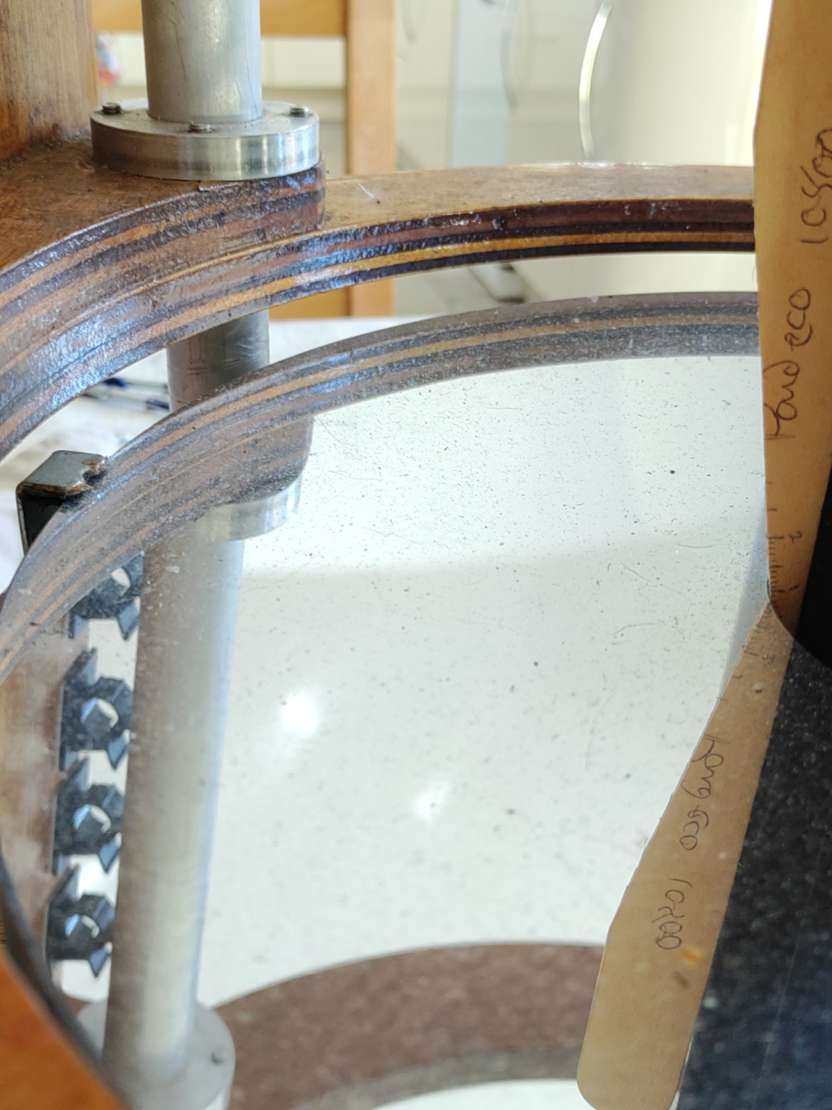
The gap between the baffle and the mirror is adjusted by moving the mirror using the mirror mount brackets, which have screw adjusters for radial in/out movement and tensioing nylon screws for fine tuning. The gauge is used to measure repeatedly the difference in gap all around while the mirror is moved, until it is concentric all around, i.e. the wedge reaches into the gap the same distance all around the mirror hole. Align the primary with the mechanical axisThe next step is to place a circular card with central pinhole in the mirror hole as a snug fit to be a viewing reference point. Using the kitchen sink collimation method' a led in the entre of a card held at the centre of curvature of the primary is used to illuminate the primary mirror and along the mechanical axis through the centre of the secondary mount hole. The pinhole in the primary allows the determination of where the axis of the telescope lies by lining the scope up with the led is reflected back to the centre of the card until the centre is directly visible through the secondary mount hole as seen from the pinhole. The light in the card at front illuminates the primary and gets reflected back to the centre of curvature back at the card. The mirror is adjusted using the primary collimation screws until the mirror reflects this back on the axis joining the pinhole and the light. I do this in the observatory by mounting the card with the light on the weather station water pipe which is almost 2* primary focal length away as required. Doing it like this also means I don't need to tip the scope on its side to collimate. Since I've already aligned the focuser and made the primary concentric to the focuser, I didn't need to use the mirror plug since the focuser was already aligned and with it ,the mirror. SO all that needed to be done was to adjust the mirror using the push screws agains the pull springs, to align it to reflect back along the optical axis onAlign the secondary mirrorThe next step is to centre the reflections from the secondary by aligning the secondary using the secondary alignment screws while viewing from the pinole. The criterion for success is that the spider vanes are reflected back on themselves and the image of the pinhole is centred in the secondary. The last step is to take this mechanically adjusted telescope and point it at a star to refine the image for fine symmetry and centring on axis. for imaging this can be done following the DSI collimation instructions or visually using the star test and rocking focus between inside and outside to make sure the expanding and compressing star image crosses the focus point evenly and symetrically. I normally touch this up using the primary mirror adjusters.Here are a few sample images to show the effect ( i believe ) of the separation not being set correctly ( or the mirrors being out of perfect prescription for correction ). Inter-mirror spacing settingThis part is about setting the mirror spacing which is one of the many crucial parameters for telescope performance. The RC optical quslity is dependent on the optical conditions for removal of spherical aberration being met. This means the spacing needs to be correct. To do this I use a ronchi eyepiece I made for the dual-pass testing of the cassegrain optics to determine the separation point
when the ronchi lines are parallel and straight. Kitchen-sink collimationThere are numerous ways to collimate a RC. All of them bar this one: link to Kitchen sink collimation article.rely on the mechanical alignment of the telescope being taken for granted, concentrating on mirror alignment only and maybe with the focuser too. However when you build your own, you need to address the issue of the mechanical components not necessarily being in alignment and needing to take actions to make this happen. In the past I might have simply followed the DSI process which DSI process which uses a camera to collimate after visual alignment or one of the many Cassegrain processes which tend to align the secondary first to centre the reflections and then the primary to fill it properly. 2nd-light Optical TrialsImaging resultsLessons Learnt |
|
![]()